4-Axis CNC Hot Wire Foam Cutter
Date: Sept 2012 - March 2013
What is it? This is a robot which can autonomously cut 3D shapes out of foam. I plan to use it cut foam wings for my airplanes. The foam cutter I used to cut wings in the past works well, but I had to cut wood templates, over which the foam cutter's hot wire passes over. Furthermore, the nichrome wire (hot wire) would snag on the wood template, which would result in a non-smooth wing. I wanted to be able to cut perfect foam wings without having to work too hard to prepare the foam (measuring foam, cutting templates, etc.).
With this CNC Foam Cutter, I just need to obtain a .txt file of the airfoils' data points, which is available online at http://www.ae.illinois.edu/m-selig/ads/coord_database.html or www.aerodesign.de/english (two files for wing root and wing tip airfoils). I also need to specify the root chord and tip chord, and that's it! In order to cut swept wings, I can manually move the hot wire to an angle and then start the foam cutting program.
Design and Build Stages:
1. Design hardware
2. Obtain all parts (aluminium parts from uncle; stepper motors from neighbour; miscellaneous parts from Home Depot)
3. Build one set of x and y axis (x1, y1 axis)
4. Design circuits (stepper drivers)
5. Build two stepper driver circuits
6. Write program for Arduino
7. Test x1, y1 axis
8. Copy x1 and y1 axis build to make x2, y2 axis
9. Build two more stepper driver circuits
10. Update code to include 4 axis
11. Test 4-axis foam cutter
Part Descriptions:

x-axis SLO-SYN stepper motor; 5 Volts; 1 A per coil
|

y-axis EAD stepper motor; 5 Volts; 2 A per coil
|

Rod holder
|

Bent aluminium; 3/8 steel rod
|
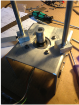
x1 and y1 Axis Build

x-axis motor bracket
|

y-axis motor bracket
|

y-axis motor bracket
|

2x4 wood screwed together; Plastic sheet on top for a smooth surface
|

Base
|

Assembled on rods
|

Use Rust Check to lube rods
|

x-axis motor mounted
|

Shafts lined up
|

x-axis coupler
|

Drill 3/8" hole for linear screw
|

y-axis rod mount
|

y-axis rod mounted
|

y-axis rods mounted
|

y-axis coupler; drilled on lathe
|

y-axis coupler screw for motor
|
y-axis coupler installed
|

y-axis linear screw installed
|

y-axis assembly complete
|

x1 y1 assembly complete
|

x-axis motor close-up
|

x-axis free end close-up
|
x2 and y2 Axis Build

After 3 hours of building
|

After 6 hours of building
|

After 9 hours of building
|

After 12 hours of building
|
Hobby Room Needs Cleaning!

Need to make space to setup CNC Foam Cutter

Cleaned Hobby Room; CNC setup in middle of room temporarily
Stepper Driver Circuit
Firstly, there are a lot of 4-axis CNC drivers available, but all of the ones I saw (under $100) use the computer's parallel port. I didn't want to setup an old computer, and I wanted to use my MacBook Pro - so I decided to use an Arduino Mega 2560 R3 micro controller and build my own stepper motor driver circuits.
Main IC: L298
I connected the L298 IC directly to 4 Arduino digital output pins. I used the following schematic, without the L297 IC, any capacitors or resistors. The L298 IC can handle 2A max, and thus, the diodes should be rated at 2A or higher. I bought 1N5400 diodes (rated at 2A) from Active Surplus at $0.75 each; each axis uses 8 diodes. The stepper motor can be controlled using this circuit and the Stepper.cpp or the AccelStepper.cpp libraries available with the Arduino IDE.
The switch on the circuit board connects all the Enable A and Enable B pins of the L298 ICs to 5V logic supply. If the switch is off, the motors will not move, so this makes a good emergency off switch.

L298 Circuit
|

Prototyping on Protoboard
|

600V 40A diodes are overkill
|

Completed two L298 circuits
|
The reason there are 600V 40A diodes in the first circuit is that there used to be smaller diodes, which after burning them out, I realized they were rated at 500 mA. I didn't have any other diodes except these 600V 40A diodes. However, I recently replaced these with 2A diodes since 2A is all I need. A guaranteed way to make sure your diodes do not burn out is to make sure the stepper motor never stalls. When the stepper stalls, it starts drawing a lot of current from the circuit as it tires to overcome the stall. This is when the circuit's components will start burning up.
The L298 IC is rated at 2A max; the y-axis motor is also rated at 2A max per coil; the x-axis motor is rated at 1A max per coil. Everything is powered by a 5V 2A max power supply.
The L298 IC is rated at 2A max; the y-axis motor is also rated at 2A max per coil; the x-axis motor is rated at 1A max per coil. Everything is powered by a 5V 2A max power supply.
Programming
I used a program called Processing to communicate with the Arduino micro controller over the computer's serial port (USB). I used this connection to send the airfoil coordinates from the computer to the Arduino.
Steps:
1. Read .txt file from computer into Processing program
2. Send airfoil coordinates from Processing to Arduino via serial port (USB cable)
3. Run CNC foam cutting program on Arduino
I have modified the AccelStepper.cpp library to suit my needs. My Arduino and Processing code is attached, if you decide to copy anything, just reference me.
|
|
|
| ||||||||
Testing x1,y1 Axis
After spending a lot of time debugging my code, I finally got both x1 and y1 axis working. I tested my CNC by drawing an airfoil shape on a piece of paper. Note that the right side of the airfoil (Leading Edge) is not closed because the black marker was not mounted properly on the CNC.

Final testing of 2-axis CNC
|

Drawing e325 airfoil on paper
|
Last update: March 18, 2013
